5586-7
Netcom’s 5586-7 is a digitally tunable filter covering the frequency range of 225 to 520MHz. The filter has been designed using new commercially available high voltage drivers and a new generation CPLD, which allows for improved performance and reduced cost while at the same time providing increased functionality. A control interference is provided to accept either parallel data and strobe or serial data, clock and strobe. The filter incorporates high voltage totem-pole drivers for the PIN diode bias voltage to minimize current draw from the 100 VDC supply.
- Specifications
- Performance
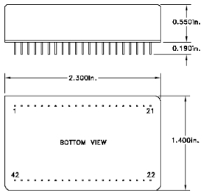
- Mechanical
- Ordering Information
- Evaluation
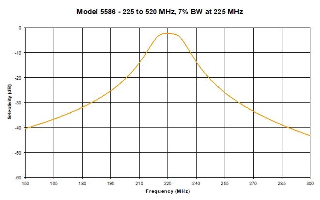
The following table shows the typical performance of the filter at different 3dB bandwidths. Options are available upon request for different bandwidth and frequency range.
| Frequency Range | 225 to 520 MHz | ||
| Available BW | 7% | ||
| *Ftune +/- 10% Rejection (Typical) | 16dB | ||
| *Ftune +/- 15% Rejection (Typical) | 22dB | ||
| *Ftune +/- 20% Rejection (Typical) | 27dB | ||
| Insertion Loss (Typical) | 3.0 dB | ||
| Impedance (Input /Output) | 50 Ω | ||
| Switching Speed, 90% RF Power | 15 µs | ||
| Tuning Channels | 250 | ||
| P1dB | 30dBm | ||
| IIP3 (+24dBm input) | +45dBm | ||
| Noise Figure (Typical) | < 1.0dB above IL | ||
| DC Inputs | |||
| +5 Volts (±0.5 Volts) | 250 mA | ||
| +100 Volts (-7, +25 Volts) | 0.2 mA (typical) 0.6 mA (maximum) |
||
| Operating Temperature Range | -40 to +85°C | ||
| Control Interface | – Selectable 8 bit Parallel or Serial – TTL and CMOS Compatible |
||
| Dimensions [L x W x H] | 2.30 x 1.40 x 0.55 inches 58.42 x 35.56 x 13.97 mm |
||
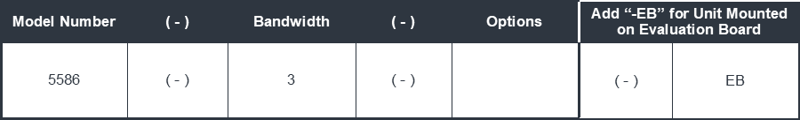
Corresponding Evaluation Board
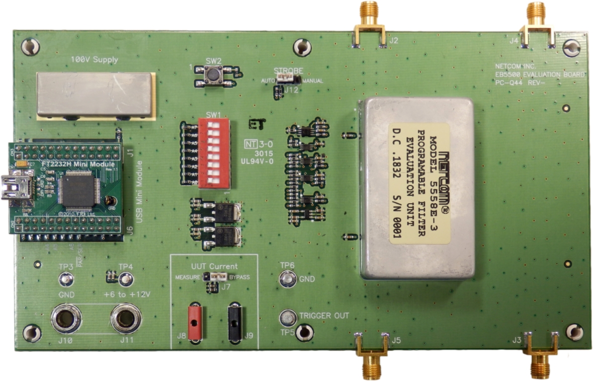
The EB5500 Evaluation Board is designed to test and evaluate Netcom’s 5586 tunable filters. The evaluation board is used to supply power to the filter, provide tuning control of the filter, and facilitate measurement of the filter’s RF parameters, switching speed and power consumption.
Pertinent tunable bandpass filters can be tuned over their frequency range using a binary switched capacitor tuning table with fixed inductors to provide the resonators, coupling and impedance matching.
The switching element is a PIN diode powered by an external nominal 100VDC supply voltage.
Tuning control of the filter is provided by the EB5500 Evaluation Board in the form of frequency words. The EB5500 uses a new USB input and user interface program to provide the frequency tuning control for the EB5500 Evaluation Board. The EB5500 Evaluation Board includes a separate RF thru path for calibration of test equipment to improve the accuracy of the RF measurements of the filter.