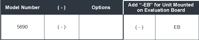
5690
Netcom’s 5690 is a tunable frequency range filter.
Unlike a regular tunable bandpass filter, where only the center frequency is adjustable, the Multi-Tune filter is a digitally programmable filter with adjustable passband between any f1 and f2 frequencies.
f1 and f2 are independently tuned at any frequency, forming a filter which has a completely adjustable center frequency and bandwidth.
This filter is offered in a small integrated SMT package to support applications where compact design, power requirements, and board layout flexibility are important.
Note: Specs Below Are for a Single 5690 Filter
- Specifications
- Performance
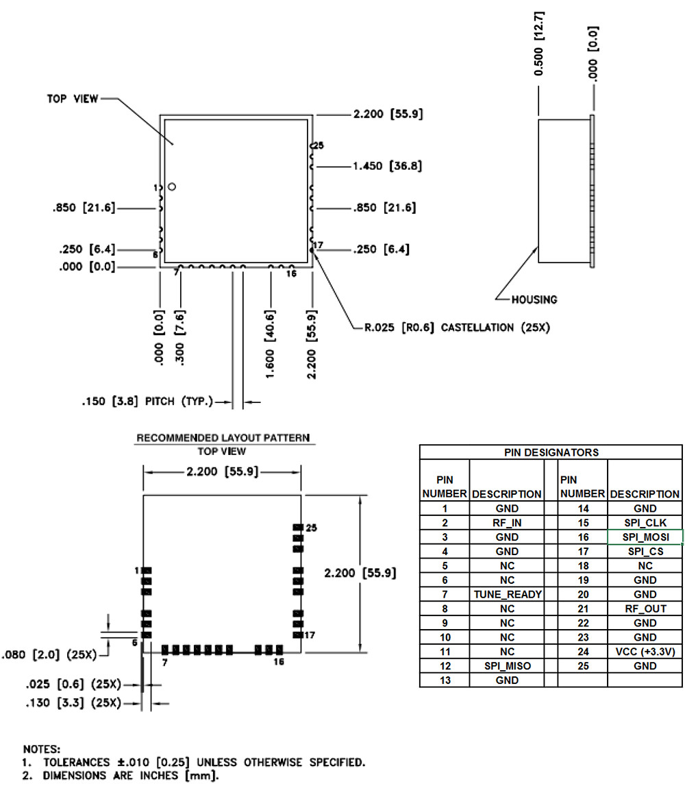
- Mechanical
- Ordering Information
- Evaluation
- Serial Address
- More Details
The following table shows the typical performance of the filter.
| Frequency Range | 1.5 to 30 MHz |
| Passband * | f1 to f2 |
| Center Frequency | (f1 + f2) / 2 |
| Impedance (Input /Output) | Typical 50 Ω |
| f1 – 5% Rejection | Between -4.5dB (max) and –6.5dB |
| f2 + 5% Rejection | Between -4.5dB (max) and –9dB |
| f1 – 10% Rejection | Between -11dB (max) and –14dB |
| f2 + 10% Rejection | Between -11dB (max) and –17dB |
| f1 – 20% Rejection | < -30dB |
| f2 + 20% Rejection | < -29dB |
| Tuning Speed | < 50 µs |
| Passband Insertion Loss (max) over wideband at Ambient Temperature | < -4dB |
| Passband Insertion Loss for narrow bandwidth (f1=f2) at Ambient Temperature | -6.5dB |
| Passband Return Loss | Between -6dB and -10dB |
| Tuning Resolution (f1 / f2) | 100KHz (min) |
| P1dB 1.5MHz to 4MHz | 29dBm |
| P1dB 4MHz to 30MHz | 30dBm |
| Max Power | 30dBm |
| IP3 1.5MHz to 4MHz | 38dBm |
| IP3 4MHz to 11MHz | 43dBm |
| IP3 11MHz to 30MHz | 48dBm |
| Estimated Spurious Level | -124dBm |
| DC Voltage | 3.3 Volts |
| DC Current Max | 50 mA |
| Operating Temperature Range | -40 to +85°C |
| Control Interface | SPI Input |
| Dimensions | 2.2 x 2.2 x 0.5 inches 55.88 x 55.88 x 12.70 mm |
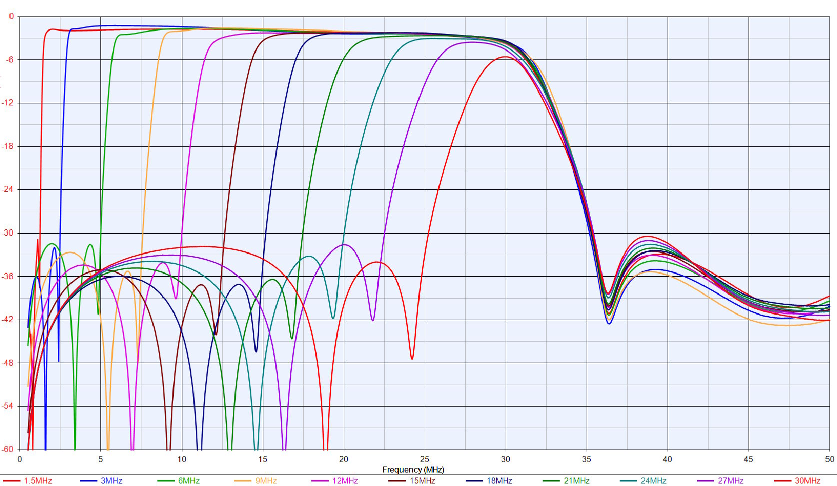
Response Plots
Typical Performance f1=1.5MHz, f2 from 1.5 to 30MHz
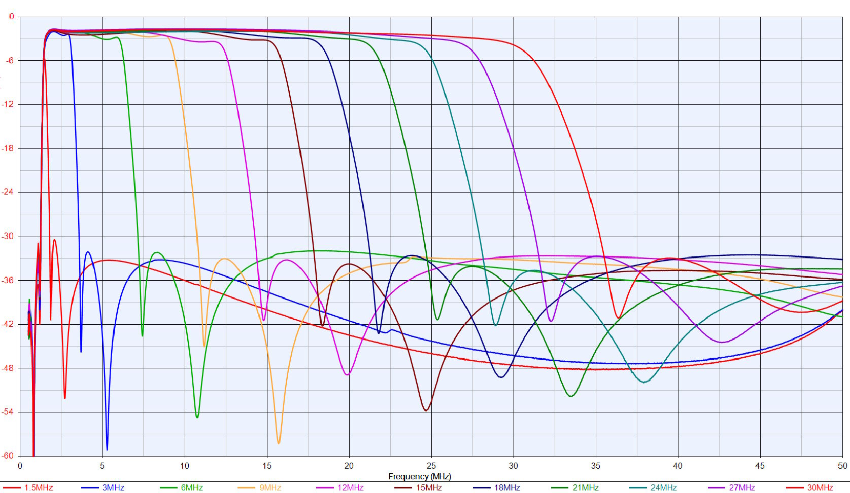
Typical Performance f1=1.5MHz, f2 from 1.5 to 30MHz
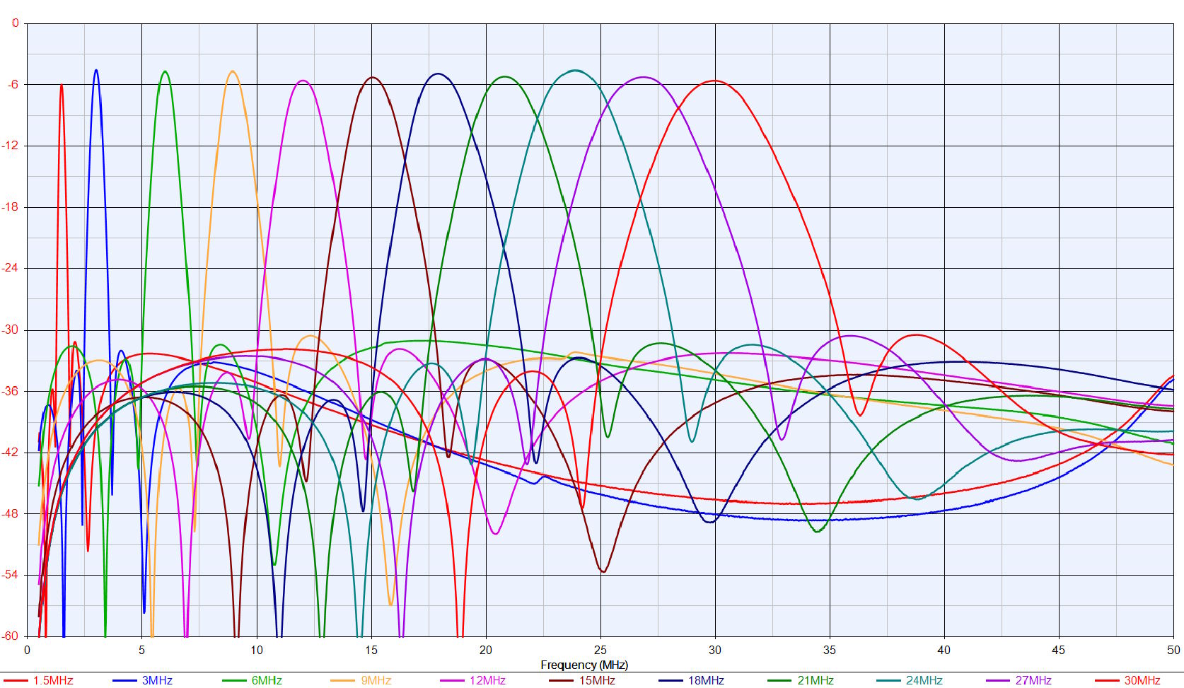
Narrowband Typical Performance f1=f2 from 1.5 to 30MHz
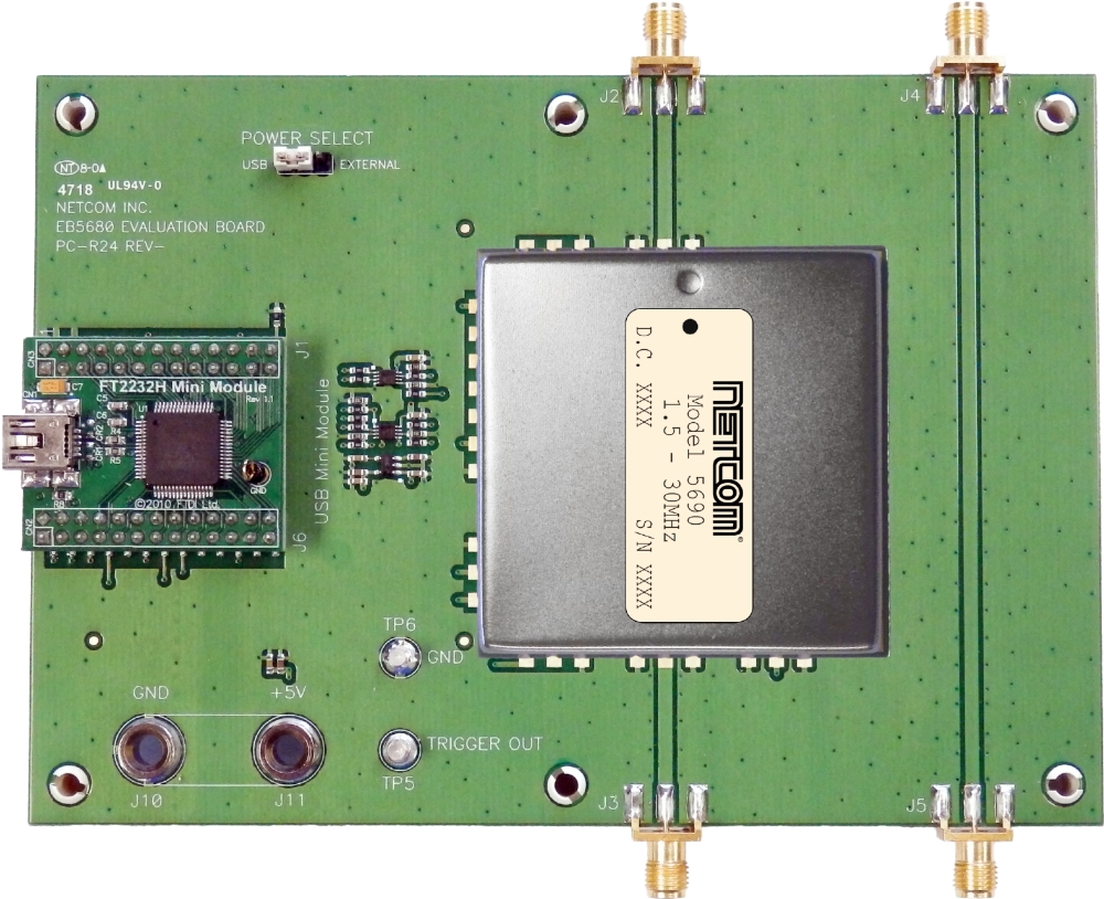
Corresponding Evaluation Board
Netcom’s 5690 is a tunable High Pass/Low Pass filter that can be tuned over the frequency range of 1.5MHz to 30MHz.
The EB5680 Evaluation Board is designed to test and evaluate Netcom’s Model 5690 Frequency Agile Filter. The evaluation board is used to supply power to the filter, provide tuning control, facilitate measurement of the filter’s RF parameters, and switching speed.
Tuning control of the filter is provided by the EB5680 Evaluation Board by a USB module and user interface program to provide frequency tuning control for the 5690 tunable filter. The EB5680 Evaluation Board includes a separate RF thru path for calibration of test equipment to improve the accuracy of RF measurements.
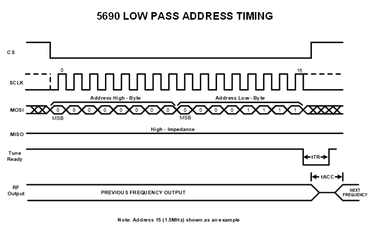
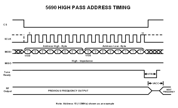
Serial Address Input Timing Diagram
Tuning addresses start at 15 decimal (1.5MHz) and end at 300 decimal (30MHz) in 100KHz increments for the Low Pass and High Pass address. Each decimal step represents a 100KHz frequency step increase or decrease. The Low Pass filter must be set at a higher frequency address than the High Pass filter frequency address . Tuning of the filter starts when the last data clock (32nd) pulse of the address is sent to the unit while the CS (Chip Select) is low.
The filter will move to the correct tune channel which allows the tuned address frequency to pass while meeting all of the tuning parameters. In some cases the filter tune channel may not move.
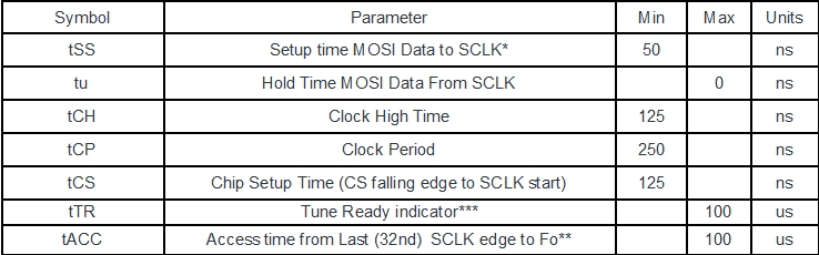
* Data clocked in on SCLK leading edge.
** Filter tunes to address on last clock bit of address SCLK.
*** Tune Ready at logic low when filter processing tuned address.
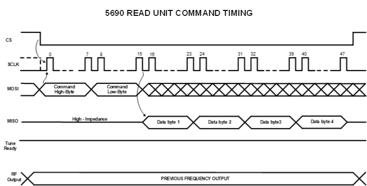
Device Commands and Addressing
The 5690 is designed to interface directly to the Serial Peripheral Interface (SPI) interface. The instructions and Addressing are listed in the table below. All instructions, addresses, and data are transferred with the MSB first and start with a High to Low transition if the SPI_CS line.
READ UNIT FW CODE1101 1100 0000 0000Unit FW RegisterRead FW code 4-letter code (ASCII)
| Instruction Name | Instruction Format | Operates On | Operation Description |
| LOW PASS ADDRESS | 0000 0000 0000 1111 – 0000 0001 0010 1100 |
Unit Address Register | Set Low Pass Address xh000F – xh012C (2) |
| HIGH PASS ADDRESS | 1001 0000 0000 1111 – 1001 0001 0010 1100 |
Unit Address Register | Set High Pass Address Xh900F – xh912C (3) |
| READ UNIT ID | 1011 0100 0000 0000 | Unit ID Register | Read 4-digit Unit ID code (ASCII) |
| READ UNIT PRODUCTION DATE | 1111 1110 0000 0000 | Unit Date Register | Read 4-digit Unit Date Code (ASCII) |
LOW PASS ADDRESS: The 5690 Multi-Tune Filter will tune the Low Pass filter cutoff when the address in the range of 15 (decimal) to 300 (decimal) is clocked into the filter. Note: The Low pass frequency must be tuned Higher than the High Pass tuned frequency.
HIGH PASS ADDRESS: The 5690 Multi-Tune Filter will tune the High Pass filter cutoff when the address in the range of 15 (decimal) to 300 (decimal) is clocked into the filter. Note: The High pass frequency must be tuned lower than the Low Pass tuned frequency.
READ UNIT ID: The 5690 Multi-Tune Filter will send a 4-digit ID “5690” in ASCII code when the command is sent to the unit. The unit will stay at the last tune channel when the command is sent.
READ UNIT FW CODE: The 5690 Multi-Tune Filter will send a 4-digit Firmware ID in ASCII code when the command is sent to the unit. The unit will stay at the last tune channel when the command is sent.
READ UNIT PRODUCTION DATE: The 5690 Multi-Tune Filter will send a 4-digit date in MMYY format in ASCII code when the command is sent to the unit. The unit will stay at the last tune channel when the command is sent.
Device Command Timing
Device Command Timing
Environmental Specification Standards
Lead Plating:
- ELECTROLESS NICKEL, TYPE 1, CLASS 1, Cu/Ni P7, 100 MICRO INCHES (0.0001 INCHES) MINIMUM, IMMERSION GOLD PLATE 2 TO 6 MICRO INCHES (0.000002 TO 0.000006 INCHES) ON OUTER LAYERS.
Temperature:
- High temperature shall meet MIL-STD-810E, Method 501.3, Procedure I to 85°C storage, and procedure II to 85°C operating.
- Low temperature shall meet Method 502.3, Procedure I to -57°C storage, and Procedure II to -40°C operating.
Vibration:
- MIL-STD-810E Method 514.4 Ground Mobile Test Procedure I, Test Condition I – 3.4.7
Shock:
- MIL-STD-810E Procedure I, Method 516.4 – Functional Shock.
Reflow:
- 245°C 15 seconds [max]
Cleaning:
- Recommend cleaning solvents used which meet ODC (Ozone Depleting Chemical) requirements.
- Solvents containing methylene chloride or other epoxy solvents should be avoided since these will attack the epoxy encapsulation material of some components.
- Ultrasonic cleaning not recommended.
Moisture Sensitivity Level:
- MSL 3