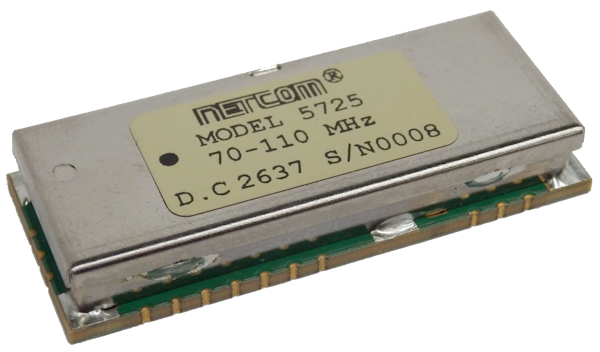
5725 Notch Filter
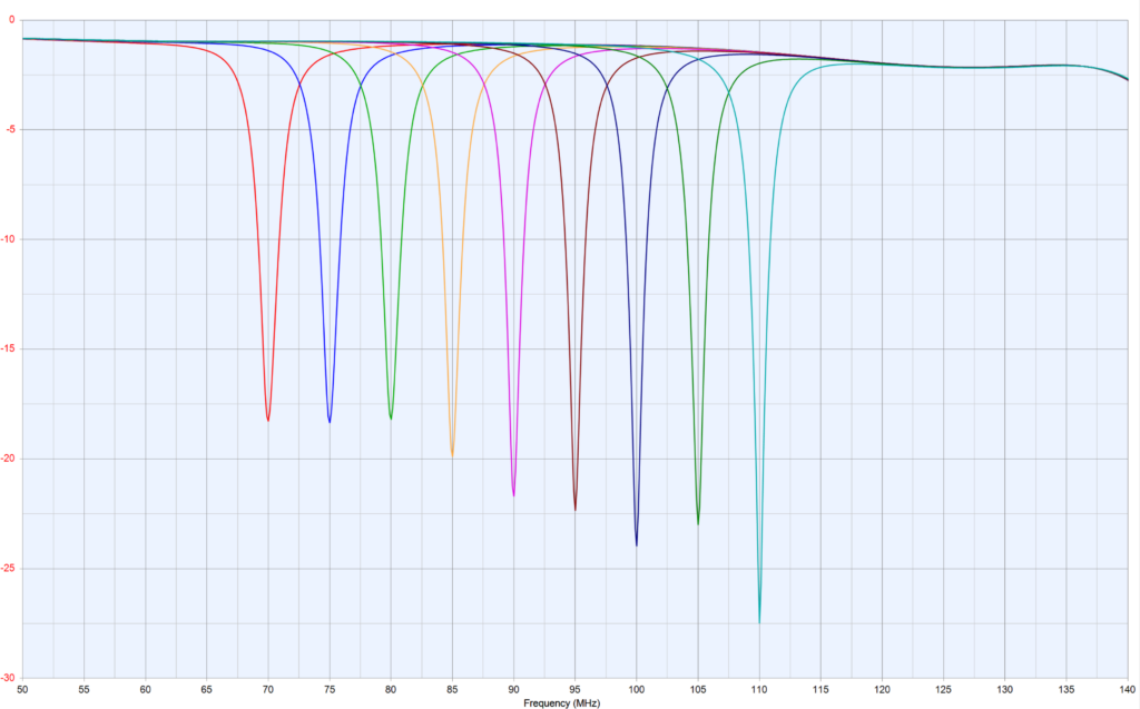
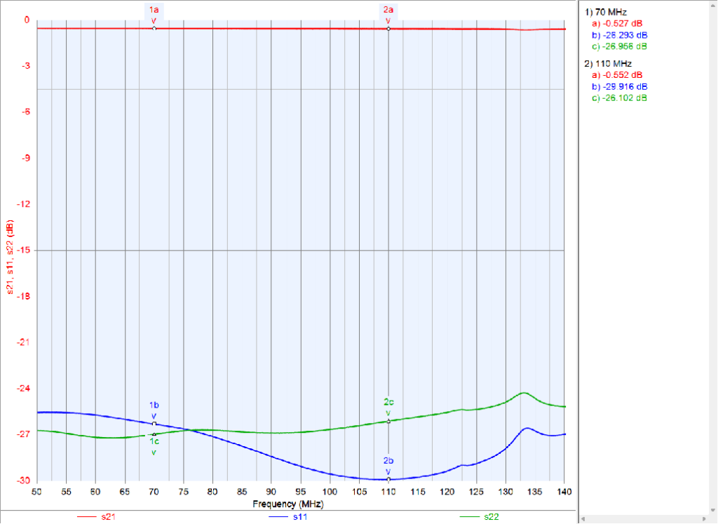
Model 5725 is a digitally tunable VHF notch filter covering 70 to 110 MHz. It carries four notches, each tuned independently over an SPI interface in 100 kHz steps, so the filter can reject up to four separate interferers at the same time, or place all four notches together at one frequency for a single deep, narrow notch. With the notches aligned, rejection is 15 dB minimum just 200 kHz from the notch center, so a wanted signal close to the interferer is left almost untouched. The same SPI interface switches the filter between active mode (notch on) and bypass mode (notch off), and any notch not in use can be parked at the high end of its range, clear of the band. Passband insertion loss is 0.5 dB typical in bypass mode, and 1.0 to 1.5 dB typical outside fnotch ±5 MHz. Internal temperature compensation holds the notch frequencies in spec from -40 °C to +85 °C. The filter handles +25 dBm input power and runs from a single 3.3 V supply. It comes in a 0.75 x 1.85 x 0.30 inch surface mount housing.
- Specifications
- Performance
- Mechanical
- More Details
| Passband Frequency Range | 70 to 110MHz |
| Tunable Notch Frequency Range (fnotch) | 70 to 110MHz |
| Notch Rejection at fnotch±200kHz | 15dB min |
| Passband Insertion Loss outside fnotch±5MHz | 1 – 1.5dB typical |
| Insertion Loss at fnotch±2.5MHz | 3.0dB typical, 4.0dB max |
| Notch Park Frequency | 120MHz |
| Impedance (Input/Output) | 50 Ω |
| VSWR | 2.5:1 |
| Temperature Range | -40°C to +85°C |
| RF Power Handling | +25dBm |
| IIP3 | +47dBm |
| DC Power | |
| DC Voltage | 3.3 VDC ±0.3 VDC |
| DC Current Max | 45mA |
| Control Interface | SPI Serial Input |
| Tuning Resolution | 100 kHz |
| Switching Speed, 90% RF Power (typical) | < 50μsec |
| Dimensions [L x W x H] | 0.75 X 1.85 X 0.30 inches
19.1 X 47.1 X 7.6 mm |
Superimposed plots every 5MHz:
Bypass mode:
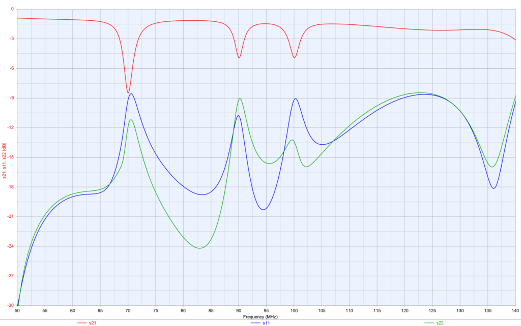
N1,N2 at 70MHz, N3 at 90MHz, N4 at 100MHz:
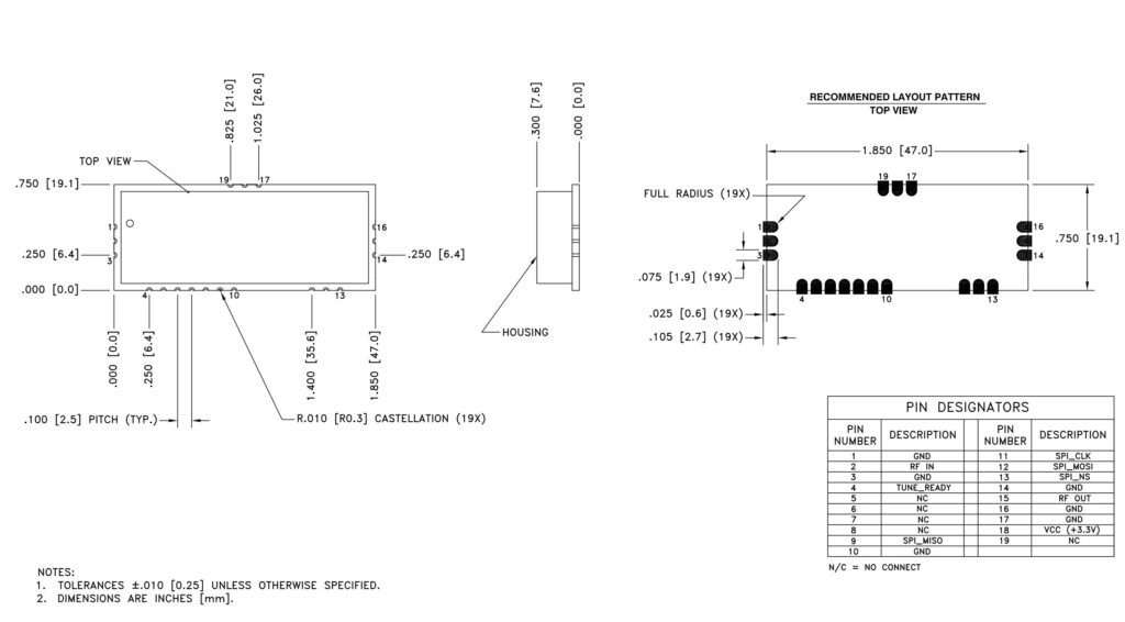
Lead Plating:
ELECTROLESS NICKEL, TYPE 1, CLASS 1, Cu/Ni P7, 100 MICRO INCHES (0.0001 INCHES) MINIMUM, IMMERSION GOLD PLATE 2 TO 6 MICRO INCHES (0.000002 TO 0.000006 INCHES) ON OUTER LAYERS.
Temperature:
- High temperature shall meet MIL-STD-810E, Method 501.3, Procedure I to 85°C storage, and procedure II to 85°C operating.
- Low temperature shall meet Method 502.3, Procedure I to -57°C storage, and Procedure II to -40°C operating.
Vibration:
- MIL-STD-810E Method 514.4 Ground Mobile Test Procedure I, Test Condition I – 3.4.7
Shock:
- MIL-STD-810E Procedure I, Method 516.4 – Functional Shock.
Cleaning:
- Recommend cleaning solvents used which meet ODC (Ozone Depleting Chemical) requirements.
- Solvents containing methylene chloride or other epoxy solvents should be avoided since these will attack the epoxy encapsulation material of some components.
- Ultrasonic cleaning not recommended.
Moisture Sensitivity Level:
- MSL 3